The System-Level Foundation of Assembly
Tracing how the CPU, OS, and ELF format shape the structure of your assembly code
We wrapped up the X86-64 assembly course last week, and I’ll be sharing notes from the sessions here as a series of articles. While the live sessions covered much more ground, I think you’ll find these write-ups valuable in their own right. I’ll be publishing them gradually over the next few weeks.
I’ll announce the next run of the course soon. Paid subscribers get early access and a discount, so upgrade now if you’d like to reserve your spot.
I’m also compiling this article series into a cleanly typeset PDF edition, available for purchase below. If you're a paid subscriber, email me for a discount code.
In the previous article, we looked at how a CPU executes instructions by fetching them from memory, decoding them, executing them, and repeating the cycle. This gave us a foundational understanding of how the hardware runs a program.
Now we can start writing some assembly programs, but jumping in immediately would mean skipping a few important abstraction layers, and that might leave some gaps in our understanding.
Specifically, an assembly program is translated into an executable binary by the assembler and the linker. That binary is then loaded into memory by the operating system so that the CPU can begin executing it. So there’s quite a bit that happens between writing assembly and running it on real hardware.
The operating system must load the executable into memory in a layout that follows the hardware’s execution model: instructions must be contiguous in memory, and instructions and data must be kept separate. To enable this layout, the executable binary must reflect this structure. Since the binary is generated from the assembly source files, the assembly program must also follow a structure that matches. All of this is linked.
In this article, we’ll trace how the structure of assembly programs is shaped by the expectations of the hardware’s execution model. We’ll follow this causal path through the operating system and the ELF file format, and explain why assembly programs are written in terms of sections and labels, like the one shown in the figure below (don’t worry if it looks alien, I promise that by the end of the article you will understand what each line of this code is doing).
By the end of the article, we will learn the following:
How the operating system structures a process's memory layout and why that structure is required
How ELF executables are structured and why they follow that layout
What sections and labels are in assembly programming and why you need to use them
Recap: Hardware's Instruction Execution Model
Let's start by doing a quick recap of the hardware's instruction execution cycle which we covered in quite detail in the previous article. This background is the foundation for everything we will learn in this article.
The processor has a special register called the instruction pointer register that contains the address of the instruction that the processor has to execute next.
The processor also has a component called the control unit that is responsible for orchestrating the execution of program instructions on the hardware. The control unit begins by fetching the instruction located at the memory address held in the instruction pointer register
The control unit then decodes the instruction to identify the opcode and the operands. For example, the opcode may be add and the operands could be the registers R8 and R9
Next,the control unit sends control signals to the register file and execution units to execute the instruction.
After this, the instruction pointer register gets incremented by the size of the current instruction so that it now has the address of the next instruction.
And this cycle repeats.
This is the hardware execution model. To enable hardware to execute your code, you must load your program’s instructions and data into memory and then update the instruction pointer with the address of the first instruction of your program.
Fortunately, we don’t need to do this ourselves, the operating system does this for us. And how the operating system does this is directly shaped by the hardware’s expectations. Let’s see how the operating system sets up a new process for execution.
Process Setup and Memory Layout
The hardware instruction execution model puts certain requirements on the OS when creating a new process:
The instruction pointer must contain the address of the first instruction of the program in memory
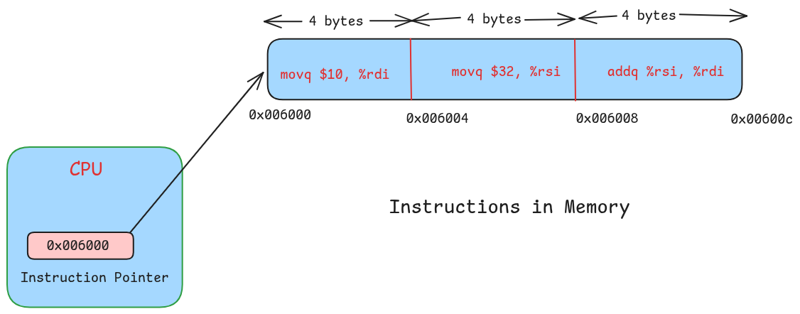
The subsequent instructions must be stored contiguously in memory. Because after the first instruction, the hardware simply increments the instruction pointer to find the address of the next one. This model requires that all instructions must be placed next to each other in memory.
Figure-2 shows this more visually, where you can see how by simply incrementing the address in the instruction pointer the CPU can advance through your program to execute it.
A third, often unstated, requirement comes from security concerns: code and data must be kept separate in memory. The hardware itself doesn’t distinguish between them, so a malicious program could modify its own data to insert harmful instructions. If the CPU then executes that data as code, it could lead to serious exploits. To prevent this, it's essential that:
Instructions are stored in a memory region with read and execute permissions, but not write
Data is stored in a separate region with read and write permissions, but not execute — except in special cases like JIT compilers

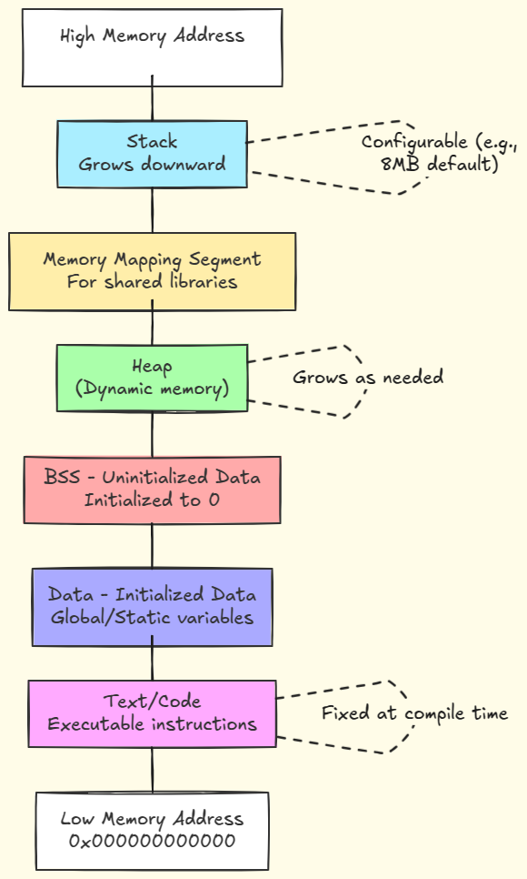
So, when the OS creates a new process, it organizes the address space layout of the process to satisfy these hardware-level requirements. The following diagram shows this layout and you can clearly see it is split into distinct memory segments, such as .text, and .data which is where program instructions and static data are stored.

You may have seen this memory layout of a process in many articles and books, but not many explain the underlying reason behind it. But now you know!
Each of these segments appear as part of a single virtual address space, but at the physical level they may be mapped to different regions of the physical memory. Each segment also has the appropriate protection bits set to ensure that the hardware doesn't end up reading and executing instructions from one of the other segments.
But creating these segments is not enough; they also need to be populated with data. For this the operating system loads the program's executable binary into memory and loads the .text segment with all the code, and the .data segment with the statically initialized data.
However, to do this efficiently, the assembler and linker must generate the executable in a format that supports fast loading. On Unix like systems, this format is the executable and linkable format (ELF), and it is designed to support fast loading of program data into the process memory. Let’s see how this format looks like from the inside.


